This project requires that the deflection of the space frame is controlled within 1/1000 under the joint action of live load and crane load. The stiffness of the space frame structure mainly depends on the thickness of the space frame, so in the design process, the double-layer welded ball space frame and the three-layer welded ball space frame are selected for trial calculation and comparison under different thickness, and the calculation results are shown in Table 1.
|
Space frame form |
Space frame thickness/m |
The maximum steel bar section/mm | Maximum spherical node diamete/mm |
Live load+Deflection of crane down (<1/1000) |
The space frame steel amount/(kg·m-2) |
| Double layer space frame | 3 | 219×14 | 900 | 1/845 | 60 |
| Double layer space frame | 3.5 | 219×14 | 1000 | 1/1020 | 56 |
| Three layer of space frame | 4 | 219×12 | 800 | 1/1201 | 55 |
| Three layer of space frame | 4.5 | 219×12 | 700 | 1/1363 | 50 |
By optimizing the comparison of the selection of the space frame, it is found that under the premise of satisfying the rigidity, the thickness of the double -layer grid shelf must reach at least 3.5m. At this time, the angle of the string pole and the abdominal rod reaches 72°, resulting in the diameter of the welding ball reaches 1m. In order to meet the pole welding requirements. At this time, the amount of steel for structural steel is not only increased, but also the difficulty of production, processing and construction and installation. In contrast, a three-layer space frame rack adds one layer of ball nodes and rods to control the angle between the string rods between 50° ~ 60°, effectively reducing the diameter of the welding ball. The three-layer welding ball space frame scheme not only can meet the design requirements, but also makes the steel volume below the double-layer space frame. In addition, the three-layer space frame have less than the double-layer space frame on the impact of crane driving, snow -accumulating effects, and uneven sensitivity of wind.
According to the results of the above comprehensive analysis, the roof of the construction drawing is designed with three-layer welded ball mesh structure, the grid size is 3.5m×4m, the edge thickness is 4.5m, and the upper chord structure is 5% slope. Through repeated design optimization and detailed calculation, the actual amount of steel used in the final space frame is about 50kg/m2, and the total amount of steel used in the main workshop is 70kg/m2. Under the premise of meeting the use function and structural safety, the project cost is effectively controlled.
3.3 Optimization of layout of structural columns
Usually the vertical column distance of steel structure rack factory is 6~9m. If the column distance increases, the span of purlin and crane beam will increase, the load area of column and beam will increase, and the structural economy will decrease. However, for the space frame structure, the most sensitive is the span and load of the structure, the size of the longitudinal column distance has relatively little influence on the grid structure, and the force transmitted by the space frame to the column is mainly vertical force, and the horizontal force is very small. Based on this, this project compares the column distance of 7m and 14m two cases. In the case of 14m column spacing, the amount of steel used in the space frame increased by less than 5%, but the amount of steel used in the columns was saved by more than 20%, and the cost of piles and foundations was correspondingly reduced. At the same time, in order to reduce the span of the wall purline, in the middle of every two structural columns to increase a wind column, the column head using spring steel plate and grid pull, make the wall purline control in a reasonable span range.
3.4 Treatment of suspended orbital nodes
According to the previous engineering experience, the space frame hanging crane often produces shaking and stuck rail in the use process, and the reason is that the rigidity of the connecting node between the suspension rail and the space frame is insufficient. In order to avoid the similar situation happening again in this project, measures are taken to strengthen the rigidity of the rail suspension nodes. The suspension rail connection nodes are shown in Figure 4. The stiffening plate along the track direction passes through the center of the ball, which can prevent the crane from vibrating during the braking process.
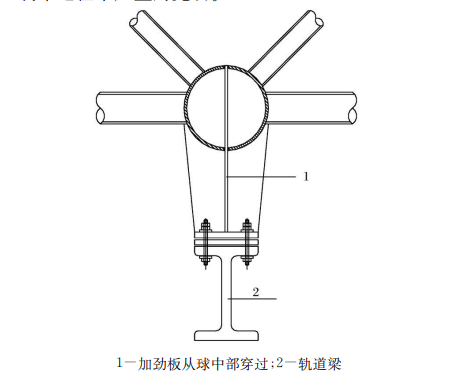
Crane track suspension point node large sample






 About Us
 2024-09-13


