


 About Us
 2022-10-31
1. Stadium Canopy Project Overview
The total construction area of the steel structure stadium is about 48,000 m², the building plane size is about 205m×227m, and the maximum height of the stadium canopy is about 32m. The roof design of the stadium stands fully draws on the tea culture. The roof supports imitate the bifurcated branches of the tea tree, and the roof canopy resembles two pieces of elegant tea leaves. The beauty of mechanics embodied by the structural stress-bearing components is organically combined with the thriving growth scene of tea trees. The architectural rendering is shown in Figure 1.
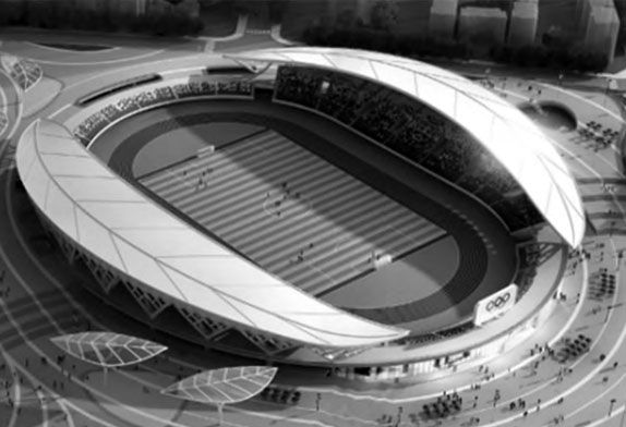
FIG. 1 Architectural rendering of the stadium
The design service life of the structure of this project is 50 years, and the dead load and live load of the shed roof are both 0.5kN/m². The basic wind pressure is 0.35kN/m². The temperature difference during the use of the steel stadium canopy structure and when the construction is closed shall be considered as +25℃ and -20℃. The seismic fortification intensity is 6 degrees, and the seismic acceleration is 0.05g.
The stadium bleacher canopy and basement use a reinforced concrete frame structure, and the entire stadium is divided into four building units along the circumferential direction through four thermal expansion joints to release thermal stress and deformation as much as possible. The stadium canopy adopts a space steel truss structure, and the arrangement of the trusses meets the modeling requirements of free-form surfaces. The steel truss and the lower concrete stand are connected by 10 tree supports, which makes the truss and the tree supports and the connection nodes between the tree supports and the stands more complicated.
2 Structural modeling and scheme comparison
2.1 Modeling of canopy structure
The stadium canopy is composed of two pieces of “tea” symmetrical about the central axis of the stadium in the north and south. and its outer contour is surrounded by 10 spatial arcs connected end to end (as shown in Figure 2(b), A1 ~ A10). The surface shape of the canopy can be controlled by adjusting the coordinate point of the center of the space arc. The support of the canopy consists of 10 connected tree-shaped struts, each of which is like a growing tea tree.
The horizontal projection length of the canopy is 196m, the maximum projection width in the middle is 32.44m, and the maximum height of the cantilevered end of the canopy from the stand support plane is 22.6m.
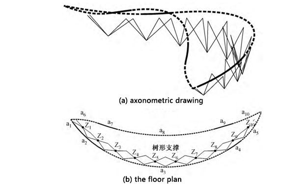
FIG. 2 Exterior outline of the building
Space frames and steel pipe trusses are two commonly used structural forms in large-span space structures. Taking into account the visual aesthetics, the main body of the bleacher canopy structure adopts the space tube truss structure, and the section of each truss is an inverted triangle. In order to facilitate the positioning of the structure during construction, each radial truss is arranged along the axis of the structure. The upper chord endpoint of the radial truss is determined by the intersection of the vertical plane passing through the center of the space frame and the given outer contour of the building. The lower chord end points of radial trusses can be obtained by translation of the corresponding upper chord endpoints.
In order to reduce the self-weight of the cantilevered part of the structure, the section height of the radial truss gradually decreases from the fixed end to the cantilevered end. At the same time, the deflection of the cantilevered end of the truss is controlled by reducing the height of the inner support point of the tree-shaped support and increasing the bending stiffness of the truss at the inner support point. The final radial truss member arrangement is shown in Figure 3. Taking the middle part of the truss structure as an example, the bleacher canopy model automatically generated by the program is a space structure (Figure 4), and the final truss model can be obtained by deleting redundant components on this basis. In addition, the radial distance between the sharp corner areas at both ends of the canopy is small, the size of the automatically generated grid is not easy to control, and the component layout of the two sharp corner areas needs to be adjusted manually.
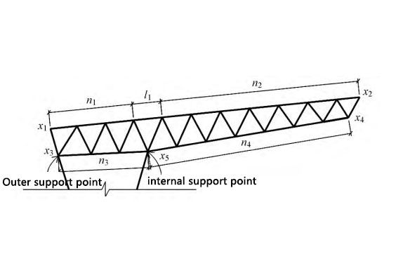
FIG. 3 Radial truss elevation
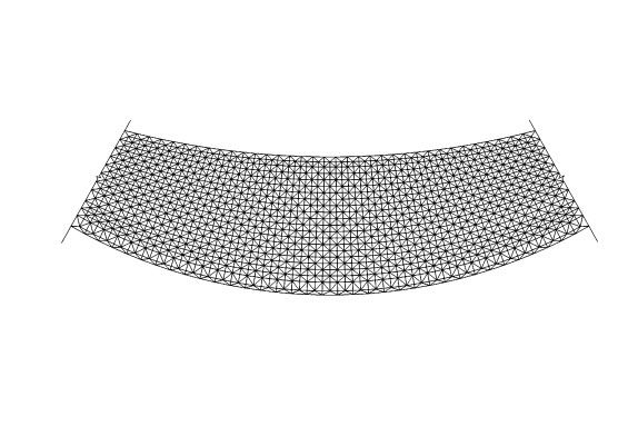
Figure 4. Stadium canopy structure
2.2 Comparison and selection of structural schemes
From the space frame structure obtained by parametric modeling to the final space tube truss structure, the following two structural schemes can be obtained according to the number of radial and hoop trusses retained (Fig. 5). (1) Scheme 1: The pipe truss is composed of 19 radial trusses and 3 circumferential trusses, and the included angle between adjacent radial trusses is 5.06°. Circumferential trusses provide out-of-plane support for radial trusses and vertical constraints for part of radial trusses, which play a supporting role.
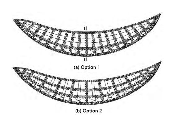
FIG. 5 Steel truss structure model
In these two schemes, the maximum cantilever length of the radial truss is 22.2m, and Q345 steel is used for truss members and tree supports. The truss members are made of round steel pipes, and the main dimensions are shown in Table 1. The tree-shaped support is made of square steel pipes with variable sections. The side length of the section changes from 1.2m at the bottom to 0.36m at the top. There are four types of tube wall thicknesses: 20, 25, 30, and 40mm.
Dimensions of truss members
|
Steel bar |
Dimension |
|
The top chord |
Φ152×8,Φ245×10,Φ299×10 |
|
The bottom chord |
Φ245×10,Φ299×16,Φ351×16,Φ351×20 |
|
The web chord |
Φ89×6,Φ127×6,Φ152×6,Φ245×10 |
Compared with scheme 1, the radial truss of scheme 2 directly falls on the tree-shaped support, and the force transmission path is direct, but the increased annular truss increases the load of the radial truss, and the reduced radial truss destroys the overall structure of the structure. sense of order. Taking into account the architectural effect and the amount of steel used, the truss arrangement of Scheme 1 is finally adopted.
(2) Scheme 2: On the basis of scheme 1, a radial truss is removed across the span, and a circumferential truss is added at the same time. The pipe truss consists of 11 radial trusses and 4 circumferential trusses, and the included angles between adjacent radial trusses are 5.06° and 11.12°. The radial truss of this scheme is directly connected with the tree support, and the hoop truss is mainly to improve the out-of-plane stability of the radial truss.


