


 About Us
 2024-07-05
3、A tension beam support system is set on the top of the independent column
Tension beams on the top of independent columns are often used in indoor gymnasiums. Generally, the gable surface is relatively high. There are concrete beams tied in one direction at the top and half height of the column to separate the masonry wall and serve as the support of the parapet wall, while the other direction is Cantilever column.
This type of space frame support is more complicated than the previous two, and it is recommended to calculate it as a whole. The difference from the second system is that under the action of temperature, the side column is a cantilever column in the long-span direction, and the stiffness can be taken as an independent column, and it can be regarded as an infinite horizontal stiffness in the tension beam direction; The tension beam can be seen to have infinite horizontal stiffness in both directions. If all fixed hinge supports are used, the space frame will be “stuck” by the tension beams at the top of the column under the action of temperature, and the assumed support scheme in Figure 1 will cause some columns to bear too much horizontal seismic force, so that the horizontal displacement on the column top is too large.
At this time, it is recommended to arrange the support according to Figure 2. Point A is a fixed hinge. The temperature deformation is that the stiffness in the Y direction is close to that of the cantilever column, and the adaptability to deformation is strong, while point B releases the horizontal displacement in the direction of the tension beam, and acts as a fixed hinge in the direction of the cantilever column. , forming a one-way sliding hinge, which can allow more bearings to transmit horizontal seismic force while releasing the temperature stress.
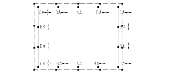
Figure 2 Schematic diagram of the layout of the support of the tension beam space frame on the top of the independent column
In principle, it is recommended to calculate the space frame and substructure of this support system according to the overall modeling. The release of the support should be accurately simulated by the spring support. The stiffness of the support is recommended to be enveloped according to the actual value. If the overall modeling is indeed difficult, when designing the space frame alone, the stiffness of the substructure and the support stiffness should be input into the model in series. For point A, it can be fixed in the X direction, and the cantilever column stiffness in the Y direction. For point B, The sliding direction can be input according to the elastic stiffness of the support, the fixed direction can be input according to the stiffness of the cantilever column, and for point C, the stiffness of the sliding support can be input according to the bidirectional support. Compared with the overall modeling, the deformation and stress of the space frame support are basically consistent.
4、Inclined column support system
Three common space frame support systems have been discussed above, but other situations are often encountered in actual engineering, such as slanted column support, especially when the horizontal stiffness of the column is relatively high. When modeling, it is assumed that the top of the slanted column is an oblique fixed hinge ( Figure 3a), but the construction drawing has made a horizontal fixed hinge (Figure 3b), resulting in the loss of the horizontal force transmitted from the original slanted column to the space frame, which will cause the original tension chord to become a compression rod and lose stable.
For the space frame supported by inclined columns, it is often equipped with a sloped curtain wall system, which needs to transmit the horizontal force at the top of the curtain wall to the space frame. At this time, it is necessary to pay attention to whether the connection structure of the curtain wall and the space frame transmits horizontal force or oblique force. In addition, the horizontal force at the top of the curtain wall will cause tension on many upper chords that are originally under compression. At this time, the envelope design should be carried out with or without the horizontal force at the top of the curtain wall.
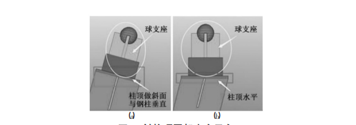
Figure 3. Inclined column support system of space frame


