1. Aircraft Hangar Project Overview
The roof structure of an aircraft maintenance hangar project is three sides supporting and one side opening (hangar gate), and the gate truss is set on the opening side. The airplane hangar span is 97m, and the depth is 80m. The roof adopts two layers of the diagonal quad-cone space frame. The maximum installation elevation of this part of the steel structure is +30.00m. According to the structural layout characteristics, site installation conditions, and the requirements of the lifting process, the lifting range of the steel structure is between 1~13 axes ×E~P axes of the structure, the height of the gate truss itself is 7.53m~9.00m, and the lifting height is about 24m. The total lifting weight of the roof and accessory structures (purlins, bridleways, gate walls, crane tracks, etc.) is 701T.

FIG.1 aircraft maintenance hangar layout
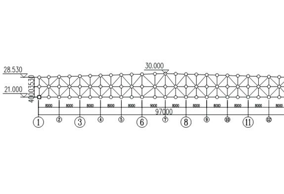 FIG.2 Front elevation view of aircraft maintenance hangar roof
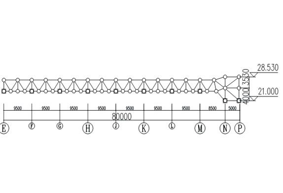
FIG.3Side elevation view of aircraft maintenance hangar roof
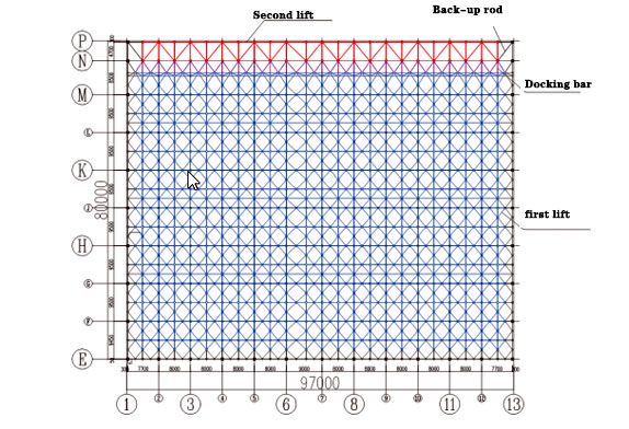
FIG.4Schematic diagram of hangar roof lifting area
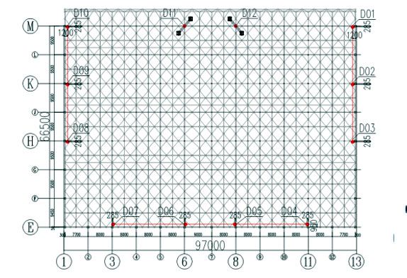
FIG.5Hangar roof first lifting point floor plan
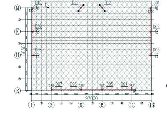
FIG.6Hangar roof second lifting point layout
2. Key construction techniques of the prefabricated hangar
In this project, the height of the space frame truss part and the roof of the truss part are different, so the traditional one-time overall lifting technology needs to assemble the space frame truss and truss combined roof into a whole on the ground, which is quite difficult. After comprehensive consideration, we decided to adopt the construction plan of two elevations. Firstly, part of the space frame roof is assembled on the ground as a whole, and then the first lift is carried out. After the lift reaches 3.0m height, the lift is suspended, part of the space frame roof is connected with part of the truss roof, and the second overall lift is carried out after the whole is formed.
2.1 Hoisting hoisting point layout
According to the floor plan (FIG. 1 aircraft hangar layout) of the roof, the position of the composite roof support, the coverage of the first lift (FIG. 4), the coverage of the second lift, and the type and power of the common hydraulic lift, the required number of lifting points can be estimated. The combined roof support should be used as much as possible when the lifting points are arranged, and a load of each hydraulic lift should be uniform. After comprehensive consideration, a total of 12 groups of lifting points are set, among which 10 groups of lifting points are set on the roof support (as shown by lifting points D01~D10 in Figure 5), and the other 2 groups of lifting points are set on the temporary lifting point support frame (as shown by lifting points D11 and D12 in Figure 5) when lifting for the first time. The second lift is moved forward to the roof support where the truss is located (lifting points D13 and D14 in FIG. 6).
2.2 Upgrade Platform Settings
Lift the platform according to lifting point and roof support. The lifting platform is fixed together with the hydraulic lift and the roof support. According to the different relative positions of the hydraulic lift and the roof support, it is divided into the first lifting platform 1 used by the lifting point in the space frame area and the second lifting platform 2 used by the lifting point in the truss area. The first lifting platform ~D10, and the second lifting platform 2 is suitable for lifting points D13 and D14. 2.3 Temporary lifting point support frame The temporary lifting point support frame is set as the lifting support in the first lifting process, which shall provide enough reaction force to the hydraulic hoist. A temporary lifting point support frame applies to lifting points D11 and D12.
2.3 Lift the airplane hangar roof twice
Part of the roof of the space frame is assembled into an overall lifting unit on the ground. The lifting point is set by using the roof support (concrete column) and temporary lifting point support frame. Auxiliary lifting tools are installed at the corresponding position of the lifting unit and lifting point, and a hydraulic lifting device is installed. The hydraulic lifting system was debugged and the trial lifting was carried out. When there was no problem with the trial lifting, the first lifting was started. The overall lifting height of part of the roof of the space frame was 3.0m, and the lifting was suspended. After the roof of the space frame part and the roof of the gate, the truss part is formed as a whole, the hydraulic hoists on the two temporary lifting points are unloaded, and the two hydraulic hoists are transferred to the second lifting platform 2 at both ends of the gate truss, and the hydraulic hoists at both ends of the gate truss are loaded to complete the transformation of the stress system of the composite roof. Remove 2 temporary lifting point supports. Start the second lift, lift the composite roof to the designed installation position as a whole, and repair the remaining post-repair rods. After the structure forms an overall force, the hydraulic hoist is unloaded, lifting equipment and temporary measures are removed, and the composite roof structure is installed.
To sum up, the two-lift construction technique of space frame truss and truss composite roof has a good application effect and the lifting process is smooth.
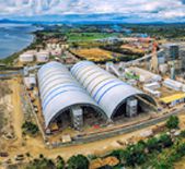
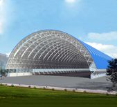
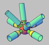
LF space frame company, as a professional aircraft hangar manufacturer, can provide customers with aircraft Hangar design and construction





 About Us
 2022-07-20


