


 About Us
 2023-02-15
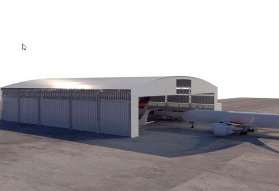
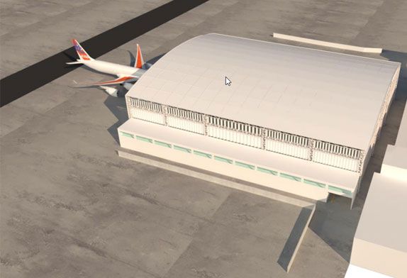
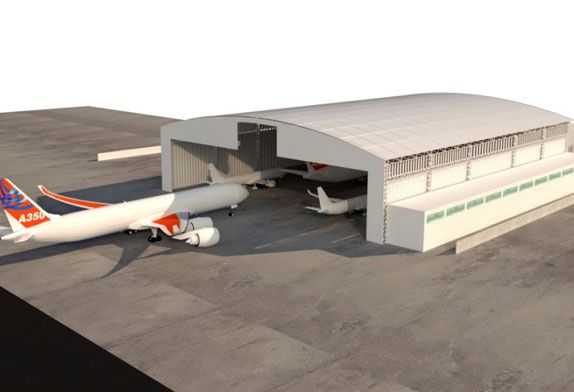
1 Aircraft Hangar Construction Project Overview
The hangar of an engineering aircraft maintenance center is a maintenance hangar that can accommodate two B737-600 aircraft at the same time. The plane size of the hangar hall is 85m×58.5m. For 50 years, the seismic fortification intensity of the building is 7 degrees, the design basic seismic acceleration value is 0.15g, and the design earthquake grouping is the first group; the seismic fortification category of the building is the key fortification category. The layout of the structure is as follows: the front side where the gate is located is all open, and the other three sides are provided with support columns. The roof structure of the hangar adopts the scheme of combining the three-layer steel pipe net frame of an obliquely placed square pyramid and the steel truss beside the gate opening. The joints are welded hollow ball joints; the gate side trusses are steel trusses connected by horizontal supports. There are 6089 rods and 1511 joints in the roof and gate truss structures; the rods are selected from 13 kinds of round steel pipes from φ60mmX3. The rods of φ180mmX10mm and above are Q355 seamless pipes, and the others are Q235 welded pipes. The height of the steel truss at the gate is 10.7m. The height of the net frame is 7.20m.
The three-sided supporting columns of the aircraft hangar structure are 25 reinforced concrete columns. Among them: 4 gate columns, using rectangular cast-in-place concrete solid columns, section 1.4mX1.0m, 2 corner columns, using square line cast reinforced concrete solid columns, section 1.2mX1.2m; 10 side columns, 9 rear columns, Rectangular cast-in-place reinforced concrete solid columns are adopted, with a section of 1.2mX0.6m; the distance between lateral columns is 5.0m to 9.0m, and the distance between supporting columns on the rear side is 8.5m; There are two inter-column support internodes for the rear columns, and the inter-column support adopts two upper and lower X-shaped supports.
2 Airplane Hangar Steel Structural Static Analysis
The constant load on the upper chord of the space frame is 0.7kN/m², and the constant load on the lower chord is the weight of the track; the live load on the roof: is 0.5kN/m²; the basic wind pressure is 0.45kN/m²; The combination of load cases is carried out according to the current load code (GB50009-2001), which considers the temperature effect (+25°C) and the horizontal and vertical seismic effects.
MSTCAD developed by the Institute of Spatial Structures of Zhejiang University is used to model the hangar roof space frame structure: in order to simplify the calculation, the lower frame columns are equivalent to elastic supports, and the supports on the top of the inter-column supports are regarded as fixed in the support plane. Therefore, the Y direction of ZZ4, ZZ5, ZZ6, ZZ20, ZZ21, and ZZ22 is set to be fixed, and the X direction of ZZ11, ZZ12, ZZ14, and ZZ15 is set to be fixed. Through the full stress optimization design of MSTCAD, the calculation results show that: the internal force in the roof structure of The rods with an absolute value greater than 600KN all appear on the gate truss, and the maximum tension of the mid-span rods is 2466.2KN. It can be seen that the gate truss bears a large vertical load, acts as a side beam that restrains the deformation of the roof structure, and provides elastic support for the free edge of the space frame. The internal force of the truss members on the inside of the hangar is slightly greater than that on the outside, indicating that the double-stick truss at the gate has good space co-working performance, and the lower chord transmits the load to the frame columns on the rear and both sides, effectively reducing the burden on the truss at the gate .
In order to ensure the normal use of the roof, this paper calculates the deflection of the roof. The maximum vertical deflection of the gate truss occurs at the mid-span position, and the maximum deflection value is 165mm; the maximum vertical deflection of the roof occurs at the mid-span of the roof and close to the gate At 1/3, the deflection is the result of the superposition of the vertical deformation of the gate truss and the mid-span of the space frame, and the maximum deflection is 176mm. It is less than the specification limit of L/300 (L is the short span of the space frame).
The static analysis results show that the roof material of the large-span hangar is relatively light, and the structure’s self-weight is relatively small. The load of the five-point suspension crane accounts for a large proportion of the total vertical load, which will have a great impact on the internal force and deformation of the structural components. ; The combination of crane loads has a controlling effect on most roof members. The internal force of the web adjacent to the node where the crane passes is very large, which is several times the internal force of the constant load and causes the opposite sign of the internal force. Therefore, the crane load is one of the main loads in the design of long-span roof structures, and the operating conditions of various cranes must be considered. To be precise, when the crane load acts on the roof truss, the most unfavorable member internal force can be calculated according to the influence surface method, while the space frame truss is a multiple statically indeterminate structure. According to the principle, the most unfavorable internal force is obtained from the spatial influence surface. However, due to the large amount of work to calculate the influence surface, and the different space frame structure forms, the influence surface is also different, which is not necessary for engineering design. Therefore, this paper still follows the most The original method and permutation and combination of various crane load positions consider the crane track as a simply supported beam fixed on the space frame, and takes the maximum value on each node. Due to the low frequency of use of the crane in the maintenance hangar, the running speed is relatively low. Slow, so the fatigue of the structure is not considered in the design.


