1 Pre-manufactured Steel Structure Stadium Project Overview
An Olympic sports center project includes supporting service facilities such as stadiums, gymnasiums, swimming pools, outdoor fitness venues, outdoor platforms, water street businesses, and elevated parking lots covered with soil. The architectural rendering of the project is shown in Figure 1. This article mainly introduces the content of stadium design.
The total construction area of the stadium is 28545m², and the auditorium capacity is 22000 seats. The stadium is composed of a canopy structure and a steel structure roof, and the overall structure has no deformation joints. A basement floor is partially set up, with a structural elevation of -6.400m. The first basement floor is mainly for athletes’ access to the stadium from the warm-up field and commercial supporting rooms; The structural elevations of the 1st to 3rd floors are -0.050, 6.550, and 10.750m respectively.

Figure 1 Project architectural renderings
2 Design standards and load values
2.1 Structural Design Standards
The designed service life of the stadium structure is 50 years. The number of seats in a single structural section of the stadium is greater than 5,000, so the seismic fortification category of the building is the key fortification category (Category B). The structural safety level is Class I, the structural importance factor is 1.1, the foundation design class is Class B, the pile foundation design class is Class B, the basement and semi-basement fire resistance class are Class I, and the superstructure fire resistance class is Class II.
2.2 Load value
During the calculation, the full-span and half-span working conditions are considered for the roof live load and snow load. Half-span loads refer to the arrangement of loads on one side of the major axis. Roof live loads are not combined with snow and wind loads at the same time.
2.2.1 Wind load
The steel structure roof is sensitive to wind load, so the basic wind pressure is 0.35kN/m² (100 years return period) when calculating the bearing capacity of the steel structure roof, and the basic wind pressure is 0.30kN when the roof is in normal use and the stand structure is calculated. /m2 (return period 50 years). The ground roughness category is Class B. The shape of the stadium is complex, and the code does not give the corresponding method for determining the shape coefficient and wind vibration coefficient. Therefore, the project conducted a wind tunnel test in accordance with the requirements of the “Code for Building Structure Loads” (GB50009-2012) (referred to as the loaded code). When calculating the main structure and envelope structure, two wind load cases are defined. Working condition 1: The parameters related to wind load are taken according to the wind tunnel test results; Working condition 2: The wind load carrier type coefficient is taken according to item 29 of load specification table 8.3.1.
2.2.2 Snow load
The steel structure roof is sensitive to snow load, so the basic snow pressure is taken as 0.45kN/m² with a return period of 100 years.
2.2.3 Earthquake action
The seismic fortification intensity of the project site is 6 degrees, the design basic seismic acceleration value is 0.05g, the design earthquake group is the first group, the construction site category is II, and the site characteristic period is 0.35s. Because the stadium is located on the edge of the slope, its east, west, and south sides are 6.6m above the terrain, according to the requirements of the “Code for Seismic Design of Buildings” (GB50011-2010) (2016 Edition), the maximum value of the horizontal seismic influence coefficient is amplified, and the amplification factor is taken as 1.4, that is, the maximum value of the horizontal earthquake influence coefficient corresponding to frequent earthquakes is 0.0583.
2.2.4 Effect of temperature
The monthly average minimum temperature of the project construction site is -3°C, the monthly average maximum temperature is 38°C, and the structure closing temperature is 13-22°C. The temperature difference between the concrete structure of the stand and the steel structure members of the roof-covered area without direct sunlight (such as radial trusses and hoop trusses) shall be ±25°C; secondary branches, space frame trusses, and platform ring trusses), considering the influence of solar radiation, the temperature difference of steel structural members is taken as -25, +30°C.
3 Stadium canopy structure
The structure plane of the stadium canopy is U-shaped, open to the north, and the second floor has the largest plane size, about 229.0m×245.1m. A reinforced concrete frame structure is adopted, consisting of a radial frame and a hoop frame, and the maximum column space frame size is 12.347m×12.925m. The embedded end of the structure is taken from the top surface of the foundation. The roof support columns within the height range of the stands are φ1500 reinforced concrete columns or φ1500 steel pipe concrete laminated columns, other frame columns are reinforced concrete columns, and the main cross-sections of reinforced concrete columns are 700×700 square columns and φ800 columns. The main sections of the rectangular frame beams of the stands are 500×700 and 400×800. The concrete strength grade of reinforced concrete columns and steel pipe concrete composite columns is C40, and the concrete strength grade of other stand structural members is C35. The overall analysis model of the stadium is shown in Figure 2, and the typical section is shown in Figure 3.
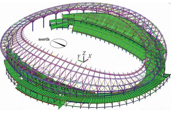
Figure.2 Steel–Built Sports Stadium
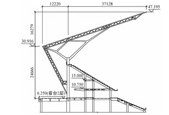
Figure.3 Steel–Supported Sports Arena
3.1 Temperature stress analysis of super-long concrete structure stands
The circumference of the inner ring of the two-story structure of the stand is about 394m, and the circumference of the outer ring is about 641m. There is no permanent structural joint, and it is an ultra-long structure. Moreover, since the stadium stand is an outdoor open-air structure, it is greatly affected by temperature. The temperature stress analysis was carried out on the 2-story concrete structure of the stand, and the calculated temperature difference was ±25°C, taking into account the decrease in structural rigidity caused by concrete cracking and the impact of concrete creep. , the temperature effect reduction factor is taken as 0.3.
3.2 Roof support columns
If the steel pipe column supporting the roof is directly extended to the foundation, the depth of the steel pipe will be larger, resulting in a corresponding increase in the thickness of the foundation, and an increase in the reinforcement of the foundation structure, which is less economical. The steel pipe column is transitioned down to steel pipe concrete column, steel pipe concrete composite column, and reinforced concrete column. Through this construction measure, the foundation thickness and reinforcement can be optimized, and the foundation thickness is no longer controlled by the steel pipe column embedment depth.
4 steel structure roof
The roof of the sports arena is in the shape of a saddle with an east-west high and a south-north low. The plane projection is approximately elliptical. The long-axis projection length of the outer contour is 246m, and the short-axis projection length is 226m. There is an approximately elliptical opening in the center of the plane. The long-axis projection length of the opening is 194.4m, the short-axis projection length of the opening is 126.2m, and the maximum cantilevered span of the roof on the plane projection is 37.357m. The elevation of the cornice is 20.200-32.500m, and the elevation of the highest point of the roof is 48.500m. The steel structure roof adopts the steel pipe truss structure supported by branch columns, which are composed of 72 planar radial trusses, 2 planar ring trusses, 2 three-dimensional ring trusses, and several supports. The steel structure sports stadium roof is supported by 32 steel pipe columns. The main distance between the steel pipe columns is about 17.7-20.2m. The top of the steel pipe column is branched to form 4 first-level branches, and the first-level branches are branched again to form 4 second-level branches. The intersection points of the second-level branches are used as the fulcrum of the radial truss. In order to provide a fulcrum for the facade space frame, part of the radial truss is extended downward along the slope formed by the space frame to form a space frame truss, and a platform ring truss is set at the bottom of the space frame truss, and the space frame truss corresponding to the steel pipe column extends downward Connected to the steel pipe column. Except for the space frame truss and the platform ring truss, the rest of the roof components are mirror-symmetrical along the X-axis and Y-axis. The maintenance track is set in the three-dimensional truss near the infield, and most of the lamps and audio equipment are set under the track.




 About Us
 2023-03-22


