In the process of promoting economic development, the construction industry plays a very important role, especially in the high-speed railway station building project. Among them, the steel structure is one of the relatively common building structures. The significant increase in steel production in the industry, coupled with the improvement of engineering technology, has gradually made steel structures popular in engineering construction. To organize steel structure construction, the overall jacking technology is a new type of technology, which has obvious advantages in many aspects such as project quality and construction efficiency.
1. Project Overview
The total construction area of the high-speed railway station building project is 38384.34m², of which the station building area is 29999 m². The roof of the waiting hall adopts a steel space frame structure. The span of the network frame is about 60m, the plane size is 138m×75.5m, the elevation of the top of the network frame is 26.2m, the cantilever length around the space frame is 9.8m, and the weight of the network frame is 696.49t. The network frame adopts the type of vertically placed quadrangular cone bolt ball node network frame, and the lower chord is supported by multiple points. The seismic fortification intensity is 7 degrees, the basic seismic acceleration value is 0.1g, and the seismic rating of the space frame structure is grade 2.
The building fire resistance level of this project is Class II, and the fire resistance limit is 1.5h. The fire resistance limit of purlins is 1.0h. The fireproofing of the steel structure part adopts the fireproofing coating technology, and the selection of the fireproofing coating and the construction process requirements must be carried out according to the fire resistance grade required by the building of this project in accordance with the requirements in the “Technical Conditions for Fireproofing Coatings for Steel Structures” (GB14907-2018).
2. The principle of overall jacking technology
The similarity between the overall jacking technology and the overall lifting process is relatively high. It is a ground-assembled jacking structure at the construction site of the high-speed rail station building. After the assembly is completed, the structure is lifted by a jack, and the unloading and installation begin after reaching the designated position. Compared with the overall jacking process, this technology has a difference in the position of the jack to avoid abnormal structural deviation during the jacking operation and enhance the stability of the jacking structure.
3. Application of integral jacking technology in steel structure construction of high-speed railway station buildings
3.1 Ground assembly
The jacking of the steel structure of the high-speed railway station building must be stable, and the construction work of the ground splicing of the jacked structure must be effectively controlled. The ground assembly is based on all incomplete unit structures and finally assembled into a whole. The stability and safety of the jacking structure during the jacking process is very important. Control the welding stress and deformation force so as not to affect the lifting effect of the structure, and can also ensure the assembly accuracy. When implementing ground assembly, remove and replace components in advance, adjust the construction site addition plan according to the actual situation, and determine whether the camber value is reasonable after determining the order of tailoring and welding. There should be no excessive vertical deviation between the jacking point and the jacking center line, and the flaw detection of key positions should be carried out in accordance with the specifications to lay the foundation for the later welding construction. The schematic diagram of the ground assembly of the space frame of the high-speed railway station building is shown in Figure 1
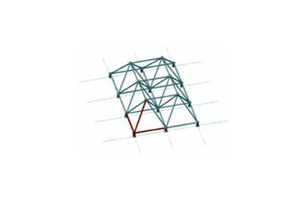
Figure 1 Schematic diagram of the ground assembly of unit space frame
3.2 Preparations
According to the layout of the jacking points on the construction site, the jacking jacks, support frames, hydraulic pump stations, steel strands, etc. required for the overall jacking construction shall be inspected and debugged in advance, and the lower jacking points and jacks must be located on the vertical axis. The error is not more than 10mm. Machine equipment debugging is carried out after power is on, through a series of operations such as oil supply and oil collection, to understand the operating status. To debug the jack, first, check the tightness of the upper and lower anchors of the cylinder, open the upper anchor, and start the main pump to run. After the extension cylinder receives the command, if the cylinder stops running, it means the operation is normal; after the retraction cylinder receives the command, if it stops, it means normal. After repeated action checks, the oil cylinder is retracted to the end, and the anchor is tightened at the same time, and the operation of the pump station can be terminated after checking that there is no error. Analyze the force and deformation of the jacking support frame and the lower jacking point. All jacking points on site must organize loading tests in a timely manner. The loading is carried out step by step for each jacking point. 20% until loaded to 100%. Analyze the force and deformation data while loading, and judge whether the data meets the requirements of the design range after evaluation. If it exceeds the design range, the cause of the problem should be analyzed in time.
3.3 Structural jacking
The jacking area of Jining North Railway Station’s space frame weighs about 440t. There are 16 sets of 40T series jacking frames in total for the space frame. The theoretical jacking weight is 640T, which meets the safety factor. According to the drawings and site conditions, the overall lifting of the network frame is divided into two areas, namely: the first area is the overall assembly unit of the -0.3m layer A-D axis / 7-14 axis space frame; the second area is the overall 2F (8.5m) floor of the station building Assembled units. First, carry out jacking in the first area, and then assemble the second area after jacking up to the position of 8.5m, and then carry out the second overall jacking after the assembly is completed. Two jacking conversion processes set temporary jacking points for conversion.
The jacking system consists of jacking brackets, hydraulic jacking jacks, jacking link rods, hydraulic pump stations, PLC control consoles, etc. Each hydraulic pump station can control two jacking jacks, and the PLC console controls each jack The displacement sensor on the pump controls the opening or closing of the solenoid valve of the oil circuit. The oil pressure of the road is read through the oil pressure gauge on the pump station, so as to convert the lift value of the road top. The jack is installed at the bottom of the jacking bracket against the At intersection of the corner lines, the jack and the jacking bracket are connected together through the jacking cap, connecting rods, and pins. The design of the jacking bracket comprehensively borrows the design concept of the space frame and the tower crane. The height of the jack body is 1.7m, and one stroke is the largest. 1.25m. The support structure is a lattice structure, the plane size is 1.0m×1.0m, and 1.0m is taken as a standard section of the jacking stroke; the total combined height is determined according to the jacking height, and the connection between the standard sections and the standard sections is connected by bolt balls, which is very easy to disassemble. convenient.
3.4 Docking and Uninstallation
After the jacking system is completed, the docking between the jacking structure and the support can be implemented. It is required to follow the order of non-jacking point support and jacking point support during the docking process. After the butt joint of the components reaches the maximum, check the joint quality and the stability of the steel structure in real-time, and start unloading after confirming that there is no problem. Pay attention to the use of measuring instruments before unloading to test the stability of the steel structure. There is no displacement of the steel structure in the vertical and horizontal directions. This is a very important condition for starting unloading. When unloading, it is simulated and calculated according to the unloading condition, and the obtained jacking reaction force results are unloaded sequentially from small to large. The unloading operation follows the basic principles of “central symmetry to the surroundings” and “overall synchronous drop in the same proportion”. Simultaneous and proportional decline” method. Before unloading, check the coordinates of all temporary support points by means of measurement review and elevation review. Use the total station to measure the elevation and position of the welding ball tops of all temporary support points, and record the data in detail to provide a basis for later adjustments.
Among all the optional unloading methods, they can be summarized as synchronous unloading and multi-stage cyclic unloading. For the synchronous unloading of steel structures in high-speed railway stations, it is recommended that the final state deflection should be evenly distributed, and the supports at the upper points of all supports should be evenly lowered to improve the transformation of the structural force system. Even if the internal force mode changes, the rules can be summarized to avoid sudden changes in the internal force of the structure due to uneven settlement, or the abnormal increase of the acting load on the temporary support to damage the structure and support. The use of synchronous unloading is difficult in the operation process. The distribution range of steel structure support points in the construction site of high-speed railway stations is relatively large, and the selection of unloading equipment is relatively complicated. The management of construction personnel must ensure coordination and synchronization accuracy. If multi-stage cyclic unloading is used, this is a compromise unloading method. The operation process is also more complicated, and the unloading space needs to be divided. The unloading of each area must be completed independently without considering the final state deflection. The jack is lowered through the displacement of the jack within the allowable range. Because of the asymmetrical and irregular characteristics of the descent, it may cause a lack of uniformity in the overall internal force distribution. According to the construction site environment and steel structure form of this high-speed rail station building project, the unloading method with the highest degree of realization is selected, and strain monitoring, stress monitoring, and deformation monitoring are carried out for the whole unloading process.
After the completion of various operations of the main structure, it is necessary to transition from the original construction stage to the actual use stage and strengthen the uniformity of internal force redistribution and the controllability of internal force changes. In addition, the unloading process must be implemented efficiently to reduce the cost and waste of the unloading process. When selecting the unloading method, the safety and economy of the construction of the high-speed railway station building should be considered.
In addition to the previous two methods, the same proportional displacement unloading method is also commonly used, but this method is not suitable for use in super-large steel structures. This type of structure has a large number of support points, and the calculation process is relatively complicated. There are differences in the lowering displacement of the jack point in each link, and the construction personnel cannot guarantee that the unloading will be completely carried out according to the displacement. To organize unloading operations, the same displacement unloading method is usually used to set the unloading displacement of each support rod in advance, and then unload according to the requirements. This unloading method is relatively simple to operate and can also ensure accuracy. In addition, in the application process of the same displacement unloading method, if the time required is too long, it is recommended to divide the steel structure into partitions, cancel the support rods in the partition and the support rods in the rear area until the unloading work on the construction site is completed.
3.5 Demolition and Simulation
The lifting of the jacking structure often requires temporary support members, and these temporary support members must be removed in time after the jacking structure is in place and the unloading is completed. To organize the removal of temporary support members, the structure boundary may change, and the internal force of the structure will also change when the support members are removed. After the temporary components are completely removed, the stress state of the structure will quickly return to the stress state in the design stage. At this time, the construction personnel simulate and calculate the dismantling process, adopt the life-death unit method, and choose to add or delete simulation units during the component installation and dismantling process, so that the process of component installation and dismantling can be simulated, and the supporting component dismantling process can be understood.
The steel structure construction of the high-speed railway station building adopts the overall jacking technology. The ground assembly, structural jacking, component unloading, temporary support component removal, etc. on the construction site need to formulate a construction plan in accordance with the technical specifications and project requirements, and give full play to the overall jacking technology. It can improve the overall stability of the steel structure, avoid deviations and mistakes during the construction process, and affect the quality of the high-speed rail station building project. It can also summarize the application experience of the overall jacking technology and provide technical support for the construction of related projects in the future.




 About Us
 2023-04-19


