1. Project Overview
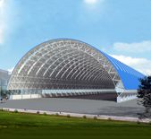
Ethiopian Airlines B747 maintenance hangar is one of the largest and most advanced aircraft maintenance hangars in Africa. The plane size of the hangar is 93.5mx96m, including the maintenance hall and the annex. Among them, the maintenance hall has a span of 81.5m, a bottom chord elevation of 19m, and a column spacing of 12m (the column spacing at the gate is 6m).
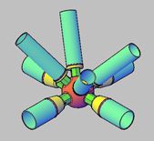
There is no hanging crane in the hangar, so the maintenance hall roof space frame adopts an orthogonal positive space frame with fewer rods, which is characterized by less steel consumption and better visual effect. space frame size 6mx6m, thickness 4m. In order to meet the needs of roof drainage, the slope of the space frame structure is 1:12. The space frame members are made of hot-rolled seamless steel pipes or welded steel pipes that meet national standards. The starting members are 9102 x 4, the largest member is 4299 x 18, and the nodes are welded balls.
The gate of the prefab hangar adopts an electric steel gate with a clear height of 18.5m. In order to meet the needs of the B747 aircraft tail entering and exiting the hangar without increasing the overall height of the structure, the roof space frame is partially raised, and a small door is set above the center of the gate. The layout of the hangar structure is shown in Figure 1. The static load of the roof of the hangar maintenance hall is 0.3kN/m², the live load is 0.3kN/m² (for calculating the main structure), and 0.5kN/m² (for calculating the roof purlin). Seismic fortification intensity is 7 degrees, Class I site, the design earthquake is grouped into the first group, and the design basic seismic acceleration value is 0.10g. The local basic wind pressure is 0.30kN/m².

Figure 1 Hangar floor plan
2 Hangar structure system layout
In the steel structure project, four inter-column supports ZC1 are arranged longitudinally in the structure as a longitudinal lateral force resistance system; in the span direction, a hinged bent frame system is formed by roof space frames and steel columns, as a lateral force resistance system in the span direction. . In order to reduce the calculated length of the steel column in the direction of the real axis and to transmit the horizontal effect of the structure, two rigid compression rods are arranged at the column head and the middle of the column. In order to meet the needs of aircraft entering and leaving the hangar, the hangar needs to be supported on three sides and open on one side. In order to provide four-side support conditions for the roof space frame, it can solve the problem of excessive deformation at the gate of the hangar and form a state of space stress. , The roof space frame at the gate of the hangar is made into a double-layer space frame.
Since the steel column at the hangar gate cannot be supported laterally, the lateral calculation length is the geometric length of the column, so the section of the steel column at the hangar gate is much larger than that in other places so that the rigidity of the entire hangar structure is The center is bound to be offset to the gate, and under the action of the horizontal earthquake, the structure will have excessive torsional deformation. In order to solve this problem, two inter-column supports ZC2 are arranged on the rear gable of the hangar, so that the center of stiffness of the structure and the center of mass is as close as possible to avoid excessive torsion of the structure under the action of horizontal force.
In the project, the length of the steel column is close to 20m, so the section of the steel column is mainly controlled by stability. The cross-section adopts double-limb lattice columns, the single-limb of the steel column is H-shaped steel, and the strips are equilateral angle steel. The distance between the legs can be adjusted to obtain the required radius of gyration of the cross-section and achieve a larger bearing capacity in this direction; due to the arrangement of two rigid compression bars in the real axis direction, the calculated length is half of the column height, which is close to the imaginary axis direction. 1/3 (the calculated length of the column in the imaginary axis direction is taken according to the bent frame system, which is 1.5 times the column height), so the section height of a single leg can be made very small. In this hangar, the single limb of the main force-bearing column is H450x200x8x12, and the column mass is only 150kg/m, which is very economical for columns with a height of nearly 20 meters and has achieved good economic benefits.
3 Overall analysis of hangar
In the previous hangar design, the upper and lower parts of the hangar were analyzed separately. First, the initial estimated column and column-to-column support horizontal stiffness is used as the support condition of the roof, and the rod and ball specifications of the roof space frame are optimized, and then the column is designed and calculated according to the support reaction force of the roof space frame.
In order to make the force analysis of the structure more accurate and the optimization of components more sufficient, the overall analysis of the upper and lower spaces was carried out, including static analysis, dynamic modal analysis, and earthquake response analysis in three directions of the hangar. The specific analysis process is as follows:
1) According to the initially estimated stiffness of the columns and the support between the columns, the rod section of the roof space frame is optimized in the space frame program SFCAD2000;
2) The geometric dimensions of the space frame, rod sections and other information are converted into People use the finite element analysis program SAP2000 and then add information such as lower columns, supports, and rigid compression rods;
3) According to the results of the overall analysis, re-correct the roof space frame members. Steel column bases are designed as split rigid bases. In the overall analysis, the connection between the steel column foot and the foundation is assumed to be a rigid connection; the steel ball of the space frame support acts on the column head and shoulder beam through the support. The connection between the roof space frame and the steel column is assumed to be hinged.
The project roof space frame adopts welded ball joints, which have a certain degree of rigidity. However, because the roof load acts on the nodes through the roof purlins, it is found through comparative analysis that the roof space frame joints are assumed to be rigid or hinged. The internal force of the cover frame rod has little effect. In the overall analysis, the nodes of the roof space frame are assumed to be hinged connections, and the space frame members are all two-force bars. The roof space frame and the single limb of the steel column are all made of Q355B steel; the material of the steel column trim strip and the rigid pressure rod are all Q235B steel.






 About Us
 2022-11-23


