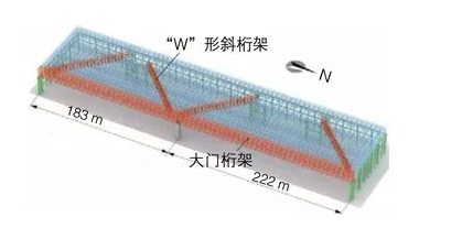
The Southern Airlines Hangar No. 1 at Beijing Daxing International Airport is currently the largest span hangar in China, with a plan dimension of 405 meters by 100 meters. The design team innovatively employed a composite structural system consisting of planar “W” shaped diagonal trusses, portal trusses, and a four-corner pyramidal grid framework. This approach significantly enhanced structural efficiency and reduced the total steel usage in the roof structure. Notably, the portal truss at the eastern side of the hangar’s opening is a key support structure for the entire roof, with a maximum span of 405 meters, a central column, and side spans of 222 meters and 183 meters, respectively (see Figure 1).
Detailed Design of Nodes
1.Overall Approach to Detailed Design
Detailed design is not merely about converting the original design drawings into construction details; it fundamentally involves verifying the overall structural safety and load-bearing capacity of critical nodes. The goal is to ensure that all members and nodes meet design requirements while optimizing the construction details of members and nodes for more practical processing and installation.
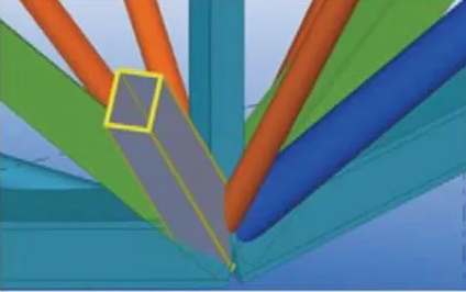
To achieve this, we employed professional BIM software for steel structures to create a three-dimensional spatial model. Considering the stress characteristics of each member and the processing conditions at the factory, we integrated connection methods and stiffener plate settings for each member. Additionally, we simulated the assembly sequence of the nodes based on their characteristics and determined the quality levels of the welds. Finally, stress analysis was conducted using Ansys software to ensure the reliability of the nodes.
2.Finite Element Calculation Analysis of Nodes
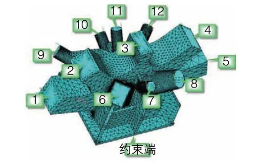
To ensure the safety of node load-bearing, we performed a computational analysis of the nodes. Ansys software was used for numerical analysis, employing Solid 95 elements for the node solid units and MPC 184 elements for section coupling to apply loads. The finite element model and mesh division are shown in Figure 7. During the calculation process, actual internal forces at the corresponding cut-off positions of each member were extracted from the original calculation model, and equilibrium forces were applied to the finite element model.
The results indicate that under the most unfavorable load combinations, most node stresses are within the elastic range (see Figure 2). The maximum equivalent stress at the corner points of the nodes is 435 MPa, which is below the ultimate tensile strength of the steel nodes and is point-distributed. Therefore, these nodes can be considered safe.
For other types of complex nodes, during the actual detailed design process, BIM three-dimensional modeling, node optimization design, and calculation review should be conducted following the above method, with corresponding detailed drawings generated to ensure that the design of the nodes is thorough before manufacturing.






 About Us
 2024-09-18


