


 About Us
 2023-03-24
1 Project Overview
The Airport building will be rebuilt and expanded according to the needs of the world’s largest passenger aircraft, the A-380, to build a new terminal building of 50,000 square meters and renovate the existing terminal building. construction of supporting facilities in the terminal area, etc. The length of runways and taxiways will be extended from 3,200 meters to 3,600 meters.
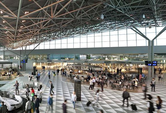
Figure 1 steel structure airport building
The roofs of the newly expanded terminal building, west concourse, and north-south concourse are all arc-shaped curved space frame structures, which are divided into 7 areas. The projected area of the space frame roof is about 32578 square meters, and the total weight is about 2000t. Our company is responsible for the construction of the new terminal building and the 1st to 4th areas of the space frame structure of the West Finger Corridor. The horizontal projected area of the space frame roof is 19166㎡ and the total weight is about 1200t. The space frame members are all Q355B seamless steel pipes, the main structure is a bolted ball node space frame, the surrounding edge trusses are pipe trusses, and the local support points are welded ball space frames. Part of the steel pipe concrete columns in the first area of the network frame and the fourth area of the network frame are connected to the roof through tree supports, and the rest of the steel pipe concrete columns are directly connected to the roof. The space frame in each area is triangular, and the elevation of the top corner of the triangle in the first area of the space frame is 34.693m, the elevation of the two bottom corners is 20.047m, and the height difference is 14.646m, as shown in Figure 2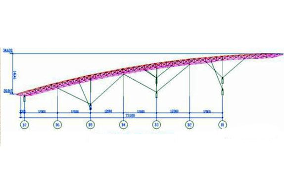
Figure 2 Side elevation of the space frame structure
The area of first area of the space frame is about 10,000 square meters, and the weight is about 600t. The structure participating in the lifting work weighs about 450t. The lower structure of the terminal building is a two-story frame concrete structure, and the elevation of the second floor is 7.300m. Assemble on layer platform. After the assembly is completed, the overall “turn over” action (hydraulic non-synchronous flip lifting) is performed on the “down” space frame, and the overall synchronous hydraulic lift is carried out after adjusting to the design posture. The control of the overturning and lifting process is the focus and difficulty of this project. A slight negligence will cause dangers such as deformation and overall bending of the space frame.

Figure 3 Space frame lifting
2 technical difficulties and key points
Through the construction of this prefabricated steel structure airport project, the key points of technical difficulties in each construction stage from deepening/optimizing design, on-site assembly, on-site welding to overall upgrading are as follows:
2.1 Deepen/optimize the design
The deepening/optimization design of this project mainly includes a unified design of welding ball specifications, handling method for overlapping and collision of rods where the diameter of welding balls becomes smaller; adjustment design of welding ball joints at the top of struts; adjustment through support stiffeners The elevation error of each column top, the method of design changing the height difference; the design and treatment of the purlin support plate at the upper chord welded ball joint; the overall analysis and calculation of the space frame structure that must be carried out after the rods are replaced.
2.2 space frame assembly
The difficulty in the overall assembly of the space frame is the elimination of accumulated errors and the spatial positioning of the lower string ball nodes;
2.3 Hydraulic lift
The technical preparations before the lifting of the space frame include: the selection of the lifting point of the space frame, the design of the lifting bracket and the lifting point, the overall lifting check of the space frame, the reinforcement of the overstressed rods, etc., each link has high technical requirements ; The control of the overall turning and lifting process of the space frame is the most difficult work in this project. The inaccurate lifting ratio of each lifting point and improper control of the lifting speed and displacement will cause serious consequences such as deformation of the space frame rods and overall bending of the space frame.
3 Construction Technology
3.1 Deepen/optimize the design
The connection between the space frame structure and the lower concrete-filled steel tube column in the bidding design drawing of this project is basically just a schematic, there is no detailed node diagram, and the space frame support form has not been specifically determined, because the lower support structure is designed prior to the space frame structure That is to say, the design of the space frame structure and the design of the lower steel pipe column are basically two parts that are completely separated.
The design software “Tube Structure Computer-Aided Design System STCAD 2.0” developed by the Institute of Structural Engineering of Shanghai Jiao Tong University is used to carry out the detailed design of the entire space frame, the design of the joints of the pipe truss and the weld check calculation. Many problems have been encountered during the detailed design process. Summarized into the following points:
3.1.1 Unified welding ball specifications and collision treatment of rods
In the original design, there are many types of welding balls and the specifications are too large (maximum Φ800×30). In order to maximize the uniform ball diameter and eliminate the protruding roof or ceiling plate due to excessive welding balls, all the welding balls in this project have a uniform diameter Adjust to Φ500, Φ600, so that individual rods with large internal force will overlap when they intersect on the welded spherical surface due to the smaller diameter of the ball (that is, the steel pipes collide), if according to the second edition of the “Steel Structure Connection Node Design Manual” The best treatment method is to use additional support plate connection processing. This process is obviously very troublesome, and the stress situation is also relatively complicated. Therefore, we refer to the principle of intersecting lines and consider the direct intersecting treatment of pipes. First, the steel pipe with a larger diameter is intersected with the welding ball, and then the steel pipe with a smaller diameter is welded with the corresponding welding ball. The line cutting machine cuts out the intersecting opening and welds the steel pipe with a larger diameter and the welding ball, so that on the one hand, the axis of the steel pipe with a small diameter passes through the center of the welding ball, and on the other hand, the weld seam meets the force requirements after the software check calculation .
3.1.2 The top node of the strut is changed to a welded ball node
In the original design, the top of the strut is intersected and welded with the lower chord of the side truss (Fig. 4). In this way, the intersection of the lower chord of the side truss must be strengthened. A casing is added outside the steel pipe, and a stiffener is added inside, which brings difficulties to the processing. Very difficult. In addition, because the diameter of the reducing tube at the end of some struts is larger than that of the lower chord of the side truss, they cannot be intersected, and the design does not allow the lower chord of the side truss to pass through the reducing tube of the strut, so we consider all welding balls here. Node processing, which not only realizes intersecting connection but also meets the force requirements through software checking.

Figure 4 Welded ball joint
3.1.3 Design of top chord welded ball purlin supporting plate
In the original design, because the diameter of the upper chord welding ball of the net frame was too large to install the roof purlins, measures as shown in Figure 5 were taken to cut the balls.
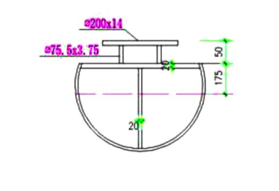
Figure.5 Welding ball chipping treatment
The disadvantage of this treatment method is that on the one hand, it is very troublesome to process, and on the other hand, the overall damage of the solder ball will have an adverse effect on the force. We finally adopted the method of adjusting the connection form of the net frame purlins to avoid damage to the main stress-bearing components, as shown in Figure 6:
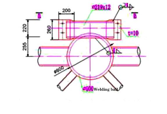
Figure.6 Space frame welding ball purlin support plate
3.1.4 Overall analysis and calculation of space frame structure after rod replacement
Since steel pipes of some specifications need to be temporarily transferred and replaced to meet production needs, and because the specifications of some rods actually used are different from the original design, it is necessary to carry out supplementary checking and calculation on the structure after the replacement of rods. Other calculation conditions for the checking calculation include but are not limited to the calculation of the 3D model, loads, boundary conditions, nodes, etc. are all taken from the original design model. Due to the slight increase in the wall thickness of the space frame members, the maximum increase in the amount of steel used in the space frame is only 3.9%, which has little impact on the structural rigidity. Under the original design conditions, except for space frame one, there are 6 D60x4 rods that exceed the design stress adjustment Except for D76x4, the other part of space frame rods all meet the design requirements. From this, the following conclusions can be drawn: in the roof space frame structure, the rods cannot be replaced at will, and the replacement of “big with small” will cause changes in stiffness, which will affect the force of the rods. to undergo rigorous analysis.
3.2 space frame assembly
3.2.1 Elimination of cumulative errors in assembly:
We have considered the existence of cumulative errors before the space frame assembly, so the space frames are assembled from the middle to the surroundings, and the total station has been used to track and monitor each control node during the entire assembly process, but after the space frame assembly is completed Afterwards, the size of the entire space frame is still lengthened. The longer the side length of the space frame, the greater the error. However, the size of the space frame accessories is within the allowable range of error, the rods are not installed incorrectly, and the bolts are all fastened in place. What is the reason? What causes the overall size of the space frame to increase? Our final analysis concluded that if the space frame rods are made with positive tolerances (considering +1mm), plus the small gaps between rods, sleeves, bolt balls and machining errors (considering +0.5mm), Taking space frame 1 as an example, the bottom side of the B7 shaft is 180m long, and there are 43 rods and 44 bolt balls in total. The cumulative error = 43*1+44*0.5*2=87mm. It can be seen that the accumulated error is very large of. Therefore, the length of the space frame rods should be as negative tolerance as possible, and the cutting amount of the bolt ball milling surface should be as positive tolerance as possible, so that the accumulated gap and length error during the assembly process of the bolt ball space frame can be completely eliminated. See Figure 7
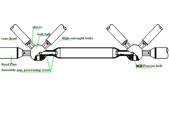
Figure.7 Space frame assembly connection
3.2.2 The location of the space frame with the bottom string ball installation node
The state of the net frame assembly in this project is the state of “down” after rotating around the B4 axis, not the design state, so the assembly positioning control point of the net frame on the floor cannot be based on the coordinates in the construction drawing. Instead, it is necessary to create a space model of the space frame structure in the computer, simulate the state of the space frame structure when it is “down” after rotation, and record the coordinates and elevation of each lower string support point, and then use a total station to accurately locate each space frame structure on the floor. The position of the bottom chord point and the height are marked, and an adjustable elevation assembly tire frame is erected at the positioning control point.
3.3 Overall hydraulic lifting technology of space frame
This project adopts the construction plan of “the overall assembly of the space frame ‘down’, hydraulic non-synchronous flip lifting, and hydraulic overall synchronous lifting”. Taking the space frame one with the largest area as an example, the lifting process of the space frame is shown in Figure 8:
Figure 8 Space frame lifting comparison


