The space frame is a new type of space structure, and its internal force distribution, mechanical performance, node reliability, and overall safety degree are not fully understood, especially when the approximate method is used to calculate, it is necessary to carry out tests in order to verify the accuracy of the calculation, and according to the test results to modify the designed bar section, in order to ensure the necessary safety degree of the structure. With the development of science and technology, new forms of space truss will appear constantly, so there are new requirements for the structure of the space frame. The purpose of the optimal design of the space frame structure is to seek a safe and economical structure, that is, to use as little material as possible to achieve the optimal stiffness, strength, and stability of the space frame structure. Therefore, it is of great practical significance to optimize the space frame structure at the initial stage of design. In this paper, the finite element method and the electrical measurement technique are used to calculate and measure the axial force of the rods of two kinds of space frame structure models respectively. The results show that the evacuated quad-cone space frame structure should be selected when considering the safety and economy of the space frame structure comprehensively.
1. Model Making
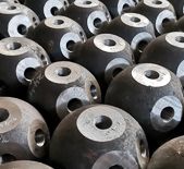
The frame model used in this paper is made of solid aluminum, with elastic modulus E= 71.7GPa, Poisson’s ratio μ= 0.33, and density ρ=2700kg/m³. The joints are formed by aluminum blocks of 6cm×6cm×6cm through saw Angle drilling. The rods are aluminum rods of 1.5cm in diameter and 40cm in length. The size of the whole space frame model is span of 2.0m, a height of 0.283m. See Figure 1.
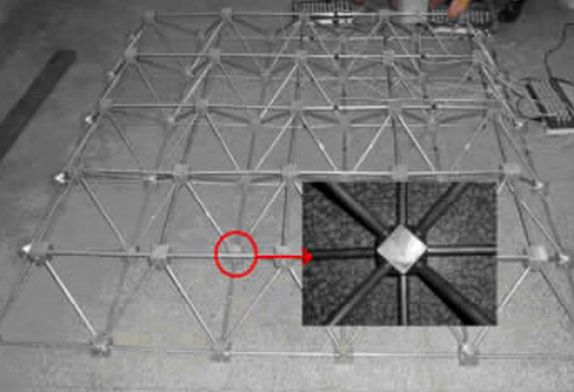
Figure 1 Overall structure of the space frame
2 Finite element Calculation
ANSYS software is used for finite element analysis, and LINK8 element is used in modeling. LINK8 element is a 3D bar element, which can bear the unidirectional tensile or compressive load. It is composed of two nodes, each node has three degrees of freedom (UX, UY, UZ), which is used to simulate the three-dimensional space truss, rope, hinge and spring in engineering structure.
For the quadrangular pyramidal space frame, in addition to the self-weight of the space frame, a concentrated load of 80N is added to each node of the upper layer. As for the evacuated quad-cone space frame, because there are fewer 4 loading nodes, the average distribution of concentrated load to each node is 95.24N. Finite element modeling was carried out for the mesh frames of the quadrangular cone and the evacuated quadrangular cone respectively, as shown in Figure 2 and Figure 3, in which the number of elements of the quadrangular cone mesh frame was 200 and that of the evacuated quadrangular cone mesh frame was 168.
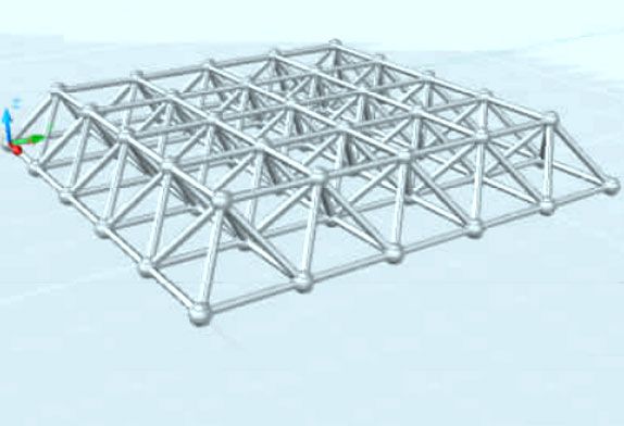
Quadrangular space frame model
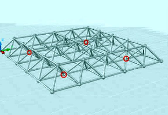
FIG. 3 Model diagram of evacuated quadrangle space frame
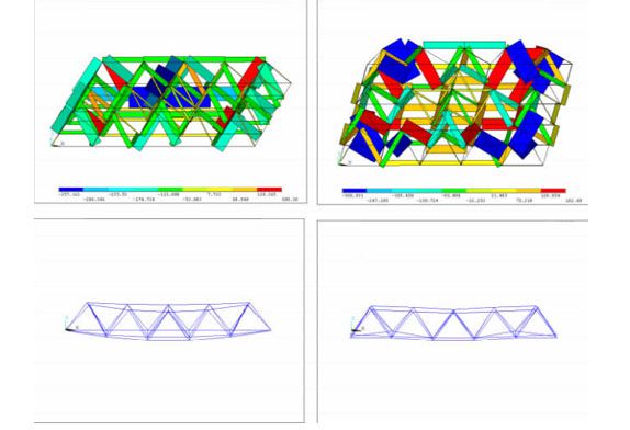
Finite element analysis was carried out by using two support modes, namely, four-point support and four-point support, and the calculated results were shown in FIG. 4 and FIG. 5. Among them, the four support points adopted by the four-point support mode are the four corner points in the middle circle of the lower node, namely the four nodes in the red circle in Figure 3.
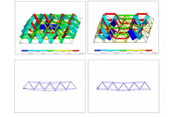
(a) four-way support and (b) four-point support
FIG. 4 Axial force diagram and displacement diagram of quadrangular pyramidal space frame under two supporting modes respectively.
(a) four-way support and (b) four-way support
FIG. 5 Axial force diagram and displacement diagram of the evacuated quad-cone space frame under two support modes respectively.
By comparing the axial force diagram in FIG. 4 and FIG. 5, it can be seen that the maximum axial force of the rod of the evacuated quad-cone mesh frame is greater than that of the quad-cone mesh frame under the two support modes. However, it is worth noting that, from the axial force results of each element calculated by ANSYS, only the axial force of a certain rod in the evacuated quad-cone mesh is greater than the maximum axial force of the rod in the quad-cone mesh. Taking the four-point support mode as an example, the maximum axial force of the rods in the quad-cone mesh frame and the quad-cone mesh frame is 300.93N and 263.42N, respectively, while only 4 rods reach the maximum axial force in the evacuated quad-cone mesh frame, and the other 164 rods are all less than the maximum axial force of the quad-cone mesh frame. And there is little difference between the axial force and that of the corresponding member in the quadrangular pyramidal space frame. That is to say, under the four-point support mode, the axial force of 2.38% of the rods in the evacuated quad-cone mesh frame exceeds the maximum axial force of the quad-cone mesh frame, but the number of rods is 16% less than that of the quad-cone mesh frame. Therefore, considering the safety and economy of the space frame, we should choose the evacuated quadrangle structure.
At the same time, by comparing the deflection charts in FIG. 4 and FIG. 5, it can also be seen that under the same support mode, the overall maximum deflection of the evacuated quadrangular cone mesh structure is greater than that of the quadrangular cone mesh structure. For the same space frame structure, the maximum deflection of the overall structure with four-point support is less than that with surrounding support. For the relatively weak stiffness of the evacuated quad-cone space frame, prestressing can be applied to improve the overall stiffness of the structure and further improve the bearing capacity of the structure.
3 Test and Measurement
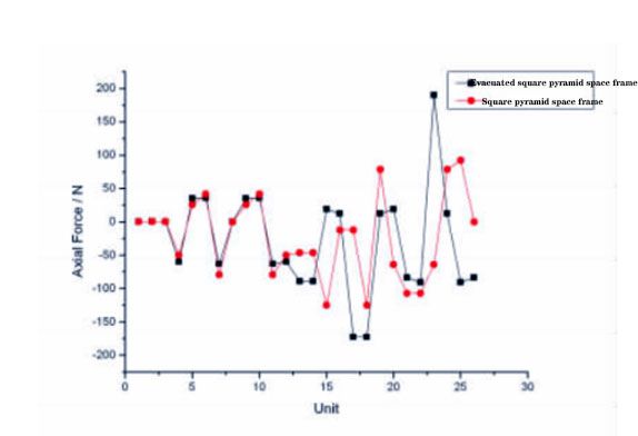
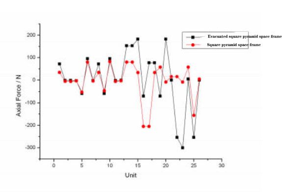
The resistance strain gauge is pasted in the middle position of each bar of the space frame, and the YJ-4501A/SZ static digital resistance strain gauge is used for measurement by using the half-bridge connection method, as shown in Figure 6. Weights are placed on each node of the upper layer of the space frame to load in stages. The four support points of the four-point support method are selected as the four corner points of the middle ring of the lower node. A total of 4 groups of test data were obtained. As shown in Figure 6, the axial forces of the rods of the quad-cone mesh frame measured under two different support modes and that of the evacuated quad-cone mesh frame are respectively compared according to the corresponding unit, and the results are as follows: no matter what kind of support mode, the axial forces of most rods of the evacuated quad-cone mesh frame are not much different from those of the evacuated quad-cone mesh frame, and only the values at individual points are greater than those of the quad-cone mesh frame. Therefore, in the practical application of engineering, it can be used to increase the strength of the elements with larger axial force on the evacuated quadrangular cone mesh frame by increasing the section size of the rod, while the other elements with smaller axial force can be used with the smaller rod, which not only saves materials but also ensures the overall strength of the space frame structure. In addition, it can be seen from the finite element analysis and test measurement data that no matter what kind of structure of the space frame, the maximum axial force of the rod and the maximum deflection of the structure under the four-point support mode are smaller than the values under the surrounding support mode. Therefore, the four-point support mode can be adopted as far as possible in practical engineering.
Four sides support
Four points support
FIG. 6 Comparison curves of axial force data of the truss rod measured under two different support modes
4 Conclusion
1) Compared with the quadrangular pyramidal mesh structure, the number of rods is reduced, the material is saved and the weight of the structure is also reduced. The axial force of the rods is not much different from that of the quadrangular mesh structure in general, but the axial force of the individual rods is greater than that of the quadrangular mesh structure. The overall deflection of the evacuated quad-cone mesh frame is slightly larger than that of the quad-cone mesh frame. The problem can be solved by applying prestress and other means. Therefore, under the circumstance of considering the safety and economy of the mesh frame comprehensively, the evacuated quad-cone mesh frame is more appropriate.
2) The axial force of the bar is affected by the space frame structure and support mode. For the space frame structure of the same structure, the axial force and structural deflection of the bar under the four-point support mode are smaller than that under the surrounding support mode.
3) According to the optimization theory of the composite space frame model, the cross-sectional area of those bars with excessive axial force can be changed to optimize the structure without increasing the number of bars, so that the overall structure tends to be reasonable and stable.




 About Us
 2023-04-14


