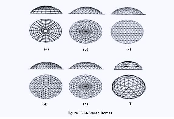
Domes are one of the oldest and most well-established structural forms and have been used in architecture since the earliest times. Dome buildings are of special interest to engineers as they enclose a maximum amount of space with a minimum surface and have proved to be very economical in terms of the consumption of construction materials. The stresses in a dome are generally membrane and compressive in most parts of the shell except for circumferential tensile stresses near the edge, and small bending moments at the junction of the shell and the ring beam. Most domes roofs are surfaces of revolution. The curves used to form the synclastic shell are spherical, parabolic, or elliptical covering circular or polygonal areas. Out of a large variety of possible types of braced domes, only four or five types proved to be frequently used in practice. They are shown in Figure 13.14.
- Ribbed domes (a)
- Schwedler domes (b)
- Three-way grid domes (c)
- Lamella domes (d, e)
- Geodesic domes (f )

Ribbed domes are the earliest type of braced domes that were constructed (Figure 13.14a). A ribbed dome consists of a number of identical meridional solid girders or trusses, interconnected at the crown by a compression ring. The ribs are also connected by concentric rings to form grids in a trapezium shape. The ribbed dome is usually stiffened by steel or reinforced concrete tension ring at its base.
A Schwedler dome also consists of meridional ribs connected together to a number of horizontal polygonal rings to stiffen the resulting structure so that it will be able to take unsymmetrical loads (Figure 13.14b). Each trapezium formed by intersecting meridional ribs with horizontal rings is subdivided into two triangles by a diagonal member. Sometimes the trapezium may also be subdivided by two cross-diagonal members. This type of dome was introduced by a German engineer, J.W. Schwedler, in 1863. The great popularity of Schwedler domes is due to the fact that, on the assumption of pin-connected joints, the structure can be analyzed astatically determinate. In practice, in addition to axial forces, all the members are also under the action of bending and torsional moments. Many attempts have been made in the past to simplify their analysis, but precise methods of analysis using computers have finally been applied to find the actual stress distribution.
The construction of a three-way space frame dome is self-explanatory. It may be imagined as a curved form of a three-way double-layer space frame(Figure 13.14c). It can also be constructed in a single layer for the dome. The Japanese “Diamond Dome” system by Tomoegumi Iron Works belongs to this category. The theoretical analysis of three-way space frame domes shows that even under unsymmetrical loading the forces in this configuration are very evenly distributed leading to an economy in material consumption.
A Lamella dome is formed by intersecting two-way ribs diagonally to form a rhombus-shaped grid pattern. As in a lamella-braced barrel vault, each lamella element has a length that is twice the length of the side of a diamond. The lamella dome can be distinguished further from parallel and curved domes. For a parallel lamella as shown in Figure 13.14d, the circular plan is divided into several sectors (usually six or eight), and each sector is subdivided by parallel ribs into rhombus grids of the same size. This type of lamella dome is very popular in the U.S. It is sometimes called a Kiewitt dome, named after its developer. For a curved lamella as shown in Figure 13.14e, rhombus grids of different size, gradually increasing from the center of the dome, are formed by diagonal ribs along the radial lines. Sometimes, for the purpose of establishing purlins for roof decks, concentric rings are introduced and a triangular network is generated.

Lamella dome
The geodesic dome was developed by the American designer Buckminster Fuller, who turned architects’ attention to the advantages of braced domes in which the elements forming the framework of the structure are lying on the great circle of a sphere. This is where the name “geodesic” came from (Figure 13.14f). The framework of these intersecting elements forms a three-way grid comprising virtually equilateral spherical triangles. In Fuller’s original geodesic domes, he used an icosahedron as the basis for the geodesic subdivision of a sphere, then the spherical surface is divided into 20 equilateral triangles as shown in Figure 13.15a. This is the maximum number of equilateral triangles into which a sphere can be divided. For domes of a larger span, each of these triangles can be subdivided into six triangles by drawing medians and bisecting the sides of each triangle. It is therefore possible to form 15 complete great circles regularly arranged on the surface of a sphere (see Figure 13.15b). Practice shows that the primary type of bracing, which is truly geodesic, is not sufficient because it would lead to an excessive length for members in a geodesic dome. Therefore, secondary bracing has to be introduced.
To obtain a more or less regular network of bracing bars, the edges of the basic triangle are divided modularly. The number of modules into which each edge of the spherical icosahedron is divided depends mainly on the size of the dome, its span, and the type of roof cladding. This subdivision is usually referred to as “frequency” as depicted in Figure 13.15c. It must be pointed out that during such a subdivision, the resulting triangles are no longer equilateral. The members forming the skeleton of the dome show slight variation in their length. As the frequency of the subdivision increases, the member length reduces, and the number of components as well as the types of connecting joints increases. Consequently, this reflects in the increase of the final price of the geodesic dome and is one of the reasons why geodesic domes, in spite of their undoubted advantages for smaller spans, do not compare equally well with other types of braced domes for larger spans.
The rise of a braced dome can be as flat as 1/6 of the diameter or as high as 3/4 of the diameter which will constitute a greater part of a sphere. For the diameter of braced domes larger than 60 m, double-layer grids are recommended. The ratio of the depth to the diameter is in the range of 1/30 to 1/50. For long spans, the depth can be taken as small as 1/100 of the diameter.
The subdivision of the surface of a braced dome can also be considered by using one of the following three methods. The first method is based on the surface of revolution. The first set of lines of division is drawn as the meridional lines from the apex. Next, circumferential rings are added. This results in a ribbed dome and further a Schwedler dome. Alternately, the initial set may be taken as a series of spiral arcs, resulting in a division of the surface into triangular units as uniform as possible. This is achieved by drawing great circles in three directions as shown in the case of a space frame dome. A noteworthy type of division of a braced dome is the parallel lamella dome which is obtained by combining the first and second methods described above. The third method of subdivision results from projecting the edges of in-polyhedra onto the spherical surface, and then inscribing a triangular network of random frequency into this basic grid. A geodesic dome represents an application of this method, with the basic field derived from the icosahedron further subdivided with equilateral triangles.


 About Us
 2021-04-27


