


 About Us
 2024-06-26
Space frame structure because of its novel structure, reasonable force, light weight, small amount of steel, a large number of steel structures have emerged from the late 1980s, increased by about 80 to 1 million m2 every year. Widely used in large sports venues, exhibition centers, theaters, shopping malls, terminal buildings, waiting halls, factory workshops, warehouses, TV towers, etc. The domestic space frame structure is mainly divided into: welding ball joint space frame and bolt ball joint space frame. The bolt ball joint space frame has a large amount of processing in the factory and convenient installation on site. It is suitable for the special-shaped structure with tight on-site construction period, restricted construction conditions and electricity consumption, complex space frame shape and difficult pole positioning. This paper focuses on the bolted ball joint space frame.
1.Decomposition of design drawings
A complete bolt ball joint space frame design drawing should include design instructions, space frame layout, upper and lower chord and web chord layout, support and bracket details, rod material table, bolt ball material table, bolt, sleeve, jackscrew material table, sealing plate, cone material table, bolt ball processing details (if other requirements, such as hanging parts, ventilation room, etc.). Firstly, the space frame plan provided in the drawing and the foundation plan are reviewed to ensure that the position of the space frame support is consistent with the foundation. Then check the rod material table provided by the space frame diagram, mainly check the axis length of the space frame, and then check the welding length of the rod according to the axis length, and then check the cutting length of the rod. After everything is correct, the bar cutting table can be drawn according to the bar material table.
Ⅱ. The calculation of the member
Bolt ball space frame rod length is controlled by bolt ball diameter, bolt ball cutting, sleeve length, cone length and other factors.
(1) Rod length calculation formula rod feeding length = rod welding length – 2 (cone head length – cone head stop length – 1mm). (In the formula, 1mm is the gap between the steel pipe and the cone head to ensure the welding quality)
The length of the rod after welding = (geometric length of the rod) – (radius of one section of ball + radius of another section of ball + length of one section of sleeve + length of another section of sleeve) + (cutting of one section of bolt ball) + (cutting of another section of bolt ball).
The geometric center length of the rod, the welding length of the rod, the feeding length of the rod, the length of the cone head, the length of the cone, the length of the segment sleeve, the cutting amount of the bolt ball, the welding reservation gap, and the detail diagram of the component combination are shown in FIG. 1. The above data have been determined in the space frame design drawing except for the length of the cone.
The length of the taper stop can be calculated according to the welding length and feeding length in the material table of the space frame rod, that is, the formula for calculating the feeding length of the rod is pushed back: the length of the taper stop = (the welding length of the rod – the feeding length of the rod) ÷2+1mm (in the formula, 1mm is the gap between the steel pipe and the taper head to ensure the welding quality).
2.The significance of the calculation of the member
(1) Check whether the welding length of the rod in the rod material table of the design drawing is accurate.
(2) Check whether the cutting length of the rod in the rod material table of the design drawing is accurate.
(3) Calculate the length of the cone according to the rod material table of the design drawing, and compare it with the cone in stock of the company or the cone in conventional use to check whether the stop length of the two is consistent. If inconsistent, measures should be taken to adjust the length of the rod cutting. Can also be customized according to the design drawing cone.
Ⅲ. Calculation of bolt ball
In the space frame design diagram, the bolt ball processing detail diagram is generally shown in Figure 2, which is the general flat bolt ball space frame ball processing diagram, which respectively represents the angle position of the space frame chord bar and the abdominal bar and the size of the corresponding bolt hole. The chord bar is cross orthogonal, and the abdominal bar position is controlled by two groups of angles, one is the intersection angle of the horizontal projection position of the abdominal bar and the chord bar. The other set is the intersection angle of the ventral rod and its projection plane. The control angles of the ventral rod in the above figure are 47°4 ‘or 42°56’ in one group and 41°49 ‘in the other group. This is shown in Figure 2. The bolt ball can be calculated according to the space frame size and space frame thickness provided by the space frame design drawing. Significance of bolt ball calculation:
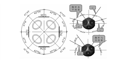
Check whether the bolt-ball processing drawing provided in the design drawing is accurate.
2. Provide bolt-ball processing drawing for lofting and guide processing.
3. Can manually calculate whether there is fighting phenomenon of the rod.
4. When there is an intersection between the truss string and the support, it provides guidance for the processing plant to weld the support and the support reinforcement plate.
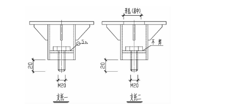
Ⅳ.The space frame support is generally Q235 steel, and the bolt ball is 45 steel. Due to the large material difference between the two, the support installation at the construction site is generally in the form of bolt connection, and the support bolts are generally used M20 ordinary bolts. The processing and installation methods of the support can be divided into two kinds: support one is the support bolt and support welding dead, the construction through the rotation of the support will be screwed into the bolt ball, the support plate must be made round; The second support bolt is not welded with the support bolt, and a hole is opened at the top of the support plate. The support bolt is screwed into the bolt ball by using the casing wrench in the construction. This is shown in Figure 3.
Ⅴ Rod processing precautions
Due to the welding shrinkage between the steel pipe and the cone head (sealing plate) in the welding process, the cutting length of the rod should be added to the welding shrinkage when drawing the bar processing material table. The value of the welding shrinkage can be calculated according to the formula, or can be obtained according to the actual measured data in the workshop.


